The Plan
In several of my previous post, I showed…
- …my setup to control LED’s using an Arduino + ESP8266. (LED’s Control Through ESP8266 + Arduino Web Page)
- …using the AppInventor environment to send a Web.PutText to send a message to the Arduino. (AppInventor2 Web Interface Trial)
- …embedding a live stream of a Foscam Wireless Camera into an AppInventor application. (Real time Wireless Camera view using AppInventor2)
My plan is to now mash up all three into one project. I will make an app that will send Web.PutText to the Arduino through the ESP8266 to trigger LED light changes and have an embedded live Foscam Wireless window all on the screen on an Android App built in the AppInventor environment.
The Android App (built in AppInventor2)
The screen layout is made up of
- 6 buttons to turn on/off 3 LED’s. The buttons are just sending custom WebPutText keywords.
- A WebViewer element which loads will load web page defined in text box element when the Go button is clicked.
- Another text box to specify the web address of the Arduino + ESP8266 system.
Here is what is looks like….

The AppInventor code to point the Web component to the ESP8266/Arduino server will set the Web1 URL to point to the web address that is entered in the corresponding text box. I was running out of screen space and didn’t want to have to add another button so I just have the code run after the address is typed into the box and something else on the screen is touched. It looks like this…

The code to start up the live camera view is really just creating a Webviewer window which will display the web site specified in the corresponding text box whenever the Go button is clicked. The rest is really up to the Foscam camera to serve up the live stream….

The LED controls are just sending some custom strings using the Web.PutText function. I am using “PtcApp” as a keyword that is not likely to be seen by the server that I can key off of. I follow up “PtcApp” keyword with a code for the {first letter of the LED color}:{1 for on / 0 for off}. The magic will happen on the upcoming Arduino code. Here is the AppInventor code….

The Arduino Code
I am only going to cover the additional Arduino code I add to implement the AppInventor functionality here. The rest of the program has been detailed in many of my previous post.
The first step is really simple. I just added another parser block to look for “PtcApp” in the incoming line from the ESP8266. I left all the previous parsing blocks and function so that all the previous features will still continue working (ie: the web page interface is still fully functional). Once the “PtcApp” is found, I call a function to parse out which color LED to control and if it is a request for On or OFF. Here is the code snips….
 if (InLine.indexOf("PtcApp ") != -1) {
    CommandQue[QueIn++]=PUT_REQUEST;    //** See next section in post for what this is for **
    ParseCustomAppRequest(InLine);
    UpdateLCDStats();
    NumberAppReq++;
    UpdateLCDStats();
 }
....
//*** This parses out the LED control strings from custom Android App and sets the appropriate state vars ***
void ParseCustomAppRequest(String InLine){
 if (InLine.indexOf("R:0")!=-1) RED_State=false;
 if (InLine.indexOf("G:0")!=-1) GREEN_State=false;
 if (InLine.indexOf("B:0")!=-1) BLUE_State=false;

 if (InLine.indexOf("R:1")!=-1) RED_State=true;
 if (InLine.indexOf("G:1")!=-1) GREEN_State=true;
 if (InLine.indexOf("B:1")!=-1) BLUE_State=true;
}
The First Test
This all actually started working very well initially. Everything worked pretty much on the first attempt, but after 5 LED change requests from the Android App, the ESP8266+Arduino stopped seeing any more requests.
Debugging the logs, I found that each PUT request was holding an additional IPD channel open. (In case you haven’t been following my previous posts, an IPD channel is the ESP8266 way of handling multiple TCP clients. Each channel corresponds to a client so the server can send messages to a specific client). The ESP8266 seems to have a limit to only be able to hold open 5 open IPD channels and then stop accepting any more connections.
I remembered another similar situation where the client wasn’t closing the connection. It was because I wasn’t sending an HTTP header back for a GET request (see the “Extra Fix” section in my post “Arduino + ESP8266 Mini Server with Command Que“). Hoping it was the same problem I made a very simple HTTP header with 0 length response and send it back each time I get a PUT request…
String PutResponse ="HTTP/1.0 200 OK \r\n"
 "Date: Fri, 31 Dec 1999 23:59:59 GMT\r\n"
 "Content-type: text/html\r\n"
 "Content-length: 0\r\n"
 "Connection: Closed\r\n"
 "\r\n";

...

 case PUT_REQUEST:
    SendCIPChunk(PutResponse,CommandQueIPD_CH[QueOut]); // Send the CIPSEND command to respond to Put request
    break;
Once I sent back the proper HTTP header, the client automatically closed the connection and all the requests from the AppInventor Web.PutText button clicks were coming in on IPD channel 0 consistently. I was able to get the LED to change +100 times through a day of testing so I think it is pretty stable now. 🙂
BTW – I will include a link at the end of this post for the full Arduino code to get the complete picture.
The Demo
Here is a short video demoing the setup…
The Arduino Code
If you want the code…
https://drive.google.com/file/d/0B1a0nPfCQQvKenVWUGtvU0RxNEU/view?usp=sharing

The delay is obviously in the video path. LED turns ON/OFF with minimal delay. Can you reduce the video resolution for less delay in the video feed?
LikeLike
Kevin,
I was thinking there might have been a delay for the LED control command to get to the Arduino through the network. I tested that and found the LED is changing almost immediately after I click the button on the Android App when connected though 4G so you were correct. The entire delay is in the camera stream path.
The camera I am using only has options for 640×480 or 320×240. I changed to 320×240 and the delay did improve from about 3 seconds to about 2 seconds. It helped for sure but then much harder to see the LCD numbers increment. Guess will have to live with one or the other.
Thanks for the suggestion.
LikeLike
Hi Peter!
I’m back! 🙂
I can finally control all my Arduino’s outputs with my App!
I have two more questions though:
1) Everytime the soft use the “AT+CLOSE=0” command to close the communication, my App displays “Error 1103: Unable to post or put the text “R:0″ with the specified…”
It works fine, but it displays this everytime the soft call the command “AT+CLOSE=0”
It’s just really annoying, that’s all…
2) My second question is:
What IP adress do you use when you are not on the same Wifi access point?
I mean if you are on the other side of the world. How can access to my ESP?
Because so far, it works only when my ESP+Mobile are on the same access point.
Thanks Peter for your help! 😉
LikeLike
Alex,
Sorry couldn’t respond earlier. Been busy with some other things….
1) Did you mean “AT+CIPCLOSE=0”? I don’t think I have use “AT+CLOSE=0” so want to make sure we are talking about the same thing. I am guessing you are sending the close command to try to close the ESP8266 channel since it seems to only be able to hold 4 open at one time. The client (your Android phone) is probably holding a channel open on every request. I also found that you can’t just send the close command to the ESP8266 channel or you will get that errors on the client side as you are seeing. You need to send back a HTTP header which will include the number of bytes the response is. The client will see the header and message and then close the connection from its side when it see a complete message. See the “Extra Fix” section in my previous post “Arduino + ESP8266 Mini Server with Command Que” posted on Dec 14, 2014.
2) To be able to access the ESP8266 when not on the same access point, you need to set up port forwarding on your router. Setting that up takes a little networking knowledge. If you are not familiar with it, it is a way to kind of open a window in your router to allow outside traffic to come in. It is a little of a security risk so I only set up port forwarding when I have a specific reason for it.
If you are thinking of trying to control your Arduino from outside the house, you will likely need to also set up port fowarding. Try Google’ing “port forwarding” along with your router model if you want to try it and not familiar with port forwarding. Each router’s menu in this area can be different so would be helpful if you can find the instructions for your specific model.
Good Luck,
Peter
LikeLike
Nice App! btw… I hope you can help me out. I have a temperature sensor to the arduino board and i want to send the values to the App inventor via ESP8266.
So how do i send a string to the app inventor and store the string in it?
LikeLiked by 1 person
Aaron,
Actually I haven’t had a need to send data out from the Arduino to a client Android app yet. I have only been taking in data from the Android app. You have just gave me an idea for my next blog post. 🙂
From a quick look on AppInvetor right now, I have a feeling it will need to use the web.get component. I have a feeling it might get complicated on the Arduino side as it will likely need to respond to a full HTTP GET request.
Maybe can get it this weekend.
Thanks,
Peter
LikeLike
thanks for your reply! 🙂
looking forward to your next project! keep it up.
Cheers,
Aaron
LikeLike
Hi Peter,
I cant find a web.get component.
Any idea of others?
LikeLike
Aaron,
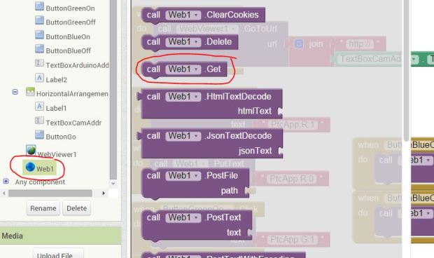
There is a Web.get component in the blocks screen. Here is a screen shot (hope it comes through in the comments section)….
Thanks,
Peter
LikeLike
THANKS PETER! 🙂 my bad. haha
LikeLike